| Rendering/ Outline Rendering |
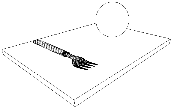
Outline RenderingThe next tutorial shows how to use outline rendering techniques of Realsoft 3D. Tutorial level: Advanced Example project: tutorprojects/rendering/outlines 1. First we model a simple test scene: a flat analytic cube (table), a sphere and a freeform object modeled using the SDS tools (a fork). You may also load the test scene: 'tutorprojects/rendering/outlineobjects'.
2. Go to the Render settings tab of the Select window and drag&drop 'Black&white outline rendering' into the view window. Render the view - the result is a two-colored image.
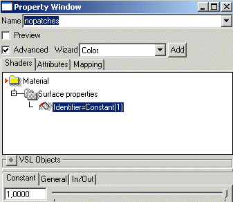
3. Let's remove the dense network of mesh boundaries from the fork object. Go to the materials tab of the select window and create a new, empty VSL material. Open the property window and rename the material as 'nopatches'. Check 'Advanced' option to see the VSL hierarchy. Also you may need to click on the '+' sign to access the VSL Objects. Drag & drop a 'Shader' object into the root level of the material. Then drag & drop a 'Constant' object into the 'Surface properties' shader. Set 'Output' channel to 'Surface:Identifier' using the popup menu of the VSL hierarchy tree. Change the assigned constant value to any nonzero value, for example 1.0. Identifier value 0 would blend the object with the background (empty space has identifier zero). If you later need to process several objects this way, just create several materials and assign value 1 in the first one, value 2 in the second one etc.
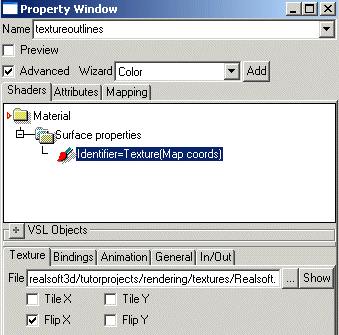
4. Make sure that the fork is selected and drag&drop the 'Nopatches' material to the view window. 5. While we are in the material editor, let's create another material which texture maps some outlines. So, create a new VSL material called 'textureoutlines'. Check the 'Advanced' option. Then apply the 'Texture map' wizard. Select the 'Texture' object from the VSL hierarchy and change the 'Output' channel again to 'Surface:Identifier'. Then pick a suitable texture file, such as 'tutorprojects/rendering/textures/realsoft.gif'. Set the 'Flip X' option. Close the property window. Then select the sphere from the view window and drag&drop the new material into the view. Note: Black texture areas will again blend with the background, and texture areas where the first subchannel (=red) value is 1.0 will blend with the fork material (its identifier was also one). It is easy to fix such conflicts without changing the actual texture map; just add a unique integer value constant to the identifier channel after reading the texture value to it:
identifier += constant(999)
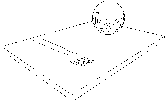
Now render the view window:
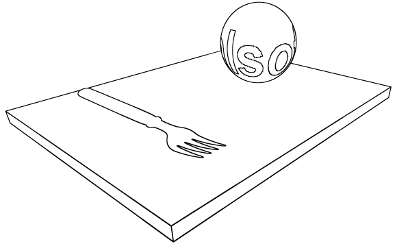
At this point, rendered outlines appear jaggy without antialiasing. We can improve quality by using a suitable post processing configuration. 6. Switch to the Post Image Effects tab of the Select window. Select 'New/Line' from the popup menu to create a line drawing effect. 7. Select 'Default effects' from the effects list and open the property window. Drag&drop the new 'Line' effect from the 'Available Effects' list to the end of 'Active effects' hierarchy. Then go to the 'Scaling' tab of the property window. Set 'Output Scale X'= 0.5, 'Output Scale Y'= 0.5. In other words, image resolution will be halved after post processing. This also has the nice side effect of making the image antialiased. Close the property window. 8. Drag&drop 'Default effects' from the select window to the view, to make sure that it will be used in rendering. Switch to the Render settings tab of the select window. Open the property window of 'Black&white outline rendering'. 'Go to the 'Post proc' tab of the property window and make sure that 'Safety area' option is checked. Without safety area, Line effect will create gaps between render boxes. Then render the view. Rendering takes now longer but the quality is better. Outlines are now probably thicker, but you can adjust the line drawing width using the 'Min. Width' attribute of the Line effect (Post Image Effects tab, property window of the Line effect). 9. As a final step, let's define varying line width. We need a channel and a material for that purpose. First go to the Channels tab of the Select window and add a new float channel called 'linewidth'. 10. Then go to the Materials tab and create a new VSL material. The contents of the material is shown in the image below:
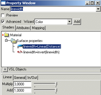
The material simply defines that line width is dependent on the distance: i.e. width increases towards the camera. 11. Go to the object hierarchy tab and select the root level. Then switch back to the material library and drag&drop 'linewidth' material to the view. Since the material was applied to the root, all objects will obey the customized line width definition. 12. Switch to the Post Image Effects tab and select the line effect. On the property window, set 'Width Channel' to the custom channel 'linewidth'. 13. Select the 'Default Effects' post image and decrease the output scaling factors to 0.25. This will improve antialiasing further so that the quality is good enough for 'final' rendering. Drag&drop the 'Default Effects' in the view window. 14. Output scaling to one quarter means that the program ray traces 16 times more pixels. To compensate the increased rendering work, select the render settings object 'Black&white outline rendering'. On the property window, go to the 'Ray Tracing' tab. Increase both 'Undersampling' values to 8 pixels. Also, make sure that 'Interpolate' is not set, it only slows the rendering without any result on the final output. Drag&Drop the render settings object 'Black&white outline rendering' in the view window. Then render the view. If necessary, adjust 'Min. Width' and 'Max. Width' values of the Line effect which define the thickness range.
|
 |
 |

